Saturday, December 29, 2012

Starcraft 2 Cybercore Badge Journal

Update January 17th 2013: Now that I am done playing with the badge it is up for sale.

So I got the idea to make a electronic badge... my idea was to make a chronoboosted cybercore.

I picked a attiny45 and decided to do charlieplexing for the leds. Here is where I found out that ATTiny is supported by a 3rd party for the Arduino IDE

The part that I picked was SMD, so for prototyping I got a DIP adapter ready with solder paste...

Time to heat up the hot air station to melt the solder paste.

Here we go

All done!


Now to prototype a circuit. I have added power and another breakout board for the programmer, as well as an led to test the blink program.


It works!


Now I need to design a pcb. The first thing is, I need to add the battery holder to my CAD program. It looks like this.


Here I have finished adding it to the CAD program. I use Eagle btw.


Time to lay out the pcb.

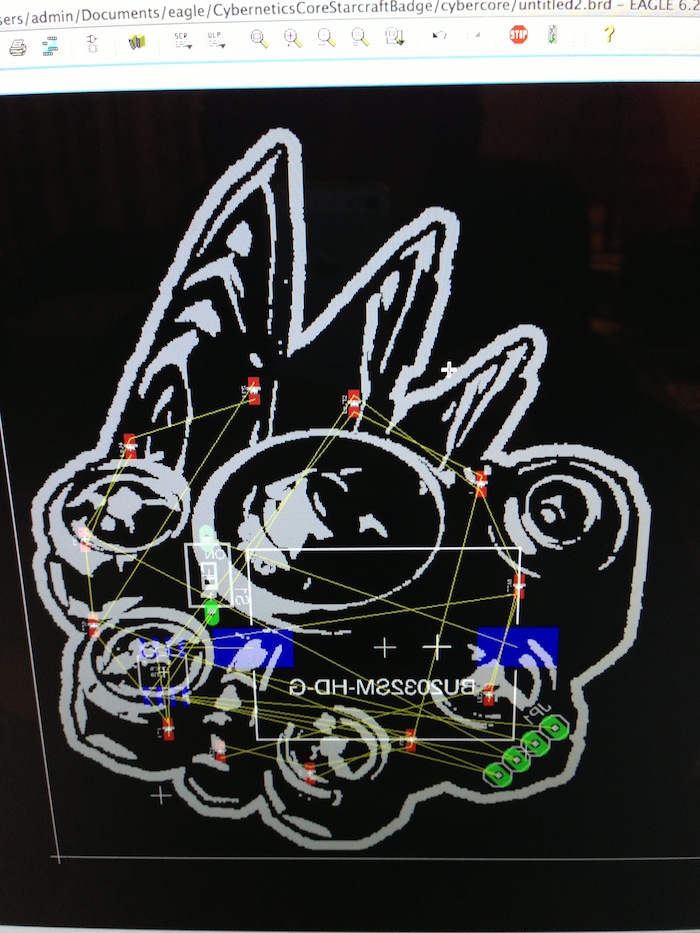
Now to route the traces.

Finish generating the files.

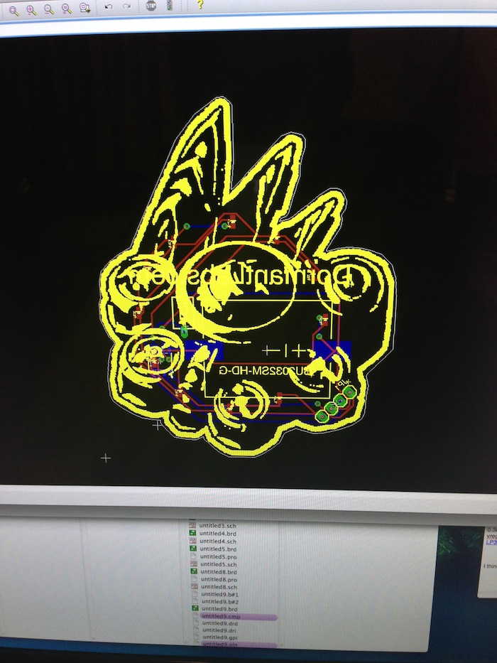
Heres a better look at the wire routing. Need to make sure that the wires don't cross inappropriately.


Ordered a set from batchpcb. Here they came in!

I have ordered parts already to populate the pcb.


So here is the pcb with solder paste applied to the led pads.

To put things in perspective, the leds are 0603 size. Not as easy to solder.


Here is the pcb with the leds placed on the solder paste.

Time to heat up the hot air station again.
All done!
Now I solder the components on the other side with a soldering iron. (If I use hot air on the opposite side then the led solder will melt and they will fall off). I used flux to solder the ATTiny.

This is how it looks with everything soldered from the top.
Funny story, when I originally ordered parts I also ordered a CR2032 battery, but mouser wanted me to pay 7$ to ship a 0.45 cent battery. They don't ship them in cheaper shipping like priority mail because they can explode and catch the package on fire, that is what the support lady told me. So I took the battery off my order. Then I went to pick up a battery the day I assembled the board, but because it was Christmas Eve, all the shops were closed. I decided to solder two power wires so I could use an external power supply.

All ready to program.
It works!

 A video is here. One thing to note is that in real life it looks more like a chronoboosted cybercore because the leds leave an after image in your eye. There also isn't any lense flare. So tomorrow I will buy a battery then cut off the power wires and glue a safety pin to it so I can wear it.


So I found some coincells in my dresser! Here is another video.

Thursday, September 13, 2012

YAMAKASI Catleap Q270 LED SE 27 Monitor is Mac Compatible

For coding, this is the same step up for me that going from a 1280x1024 to 1920x1080 made, in terms of making it easier to work. The Catleap Q270 SE is compatible with my 2009 mac mini.


You have to make sure that you have a display port to dual link dvi adapter. Whatever you have, make sure you can find a dual link dvi adapter. I am using the 99$ Apple display port to dual link dvi adapter. One thing to note is if you use this adapter, make sure to plug the usb portion of it in, otherwise it will not work.


The monitor comes with it's own power brick.


One thing to note is that if you turn the monitor off for some time, and then turn it back on, there is some fuzziness, which can be solved by unplugging the dual link dvi cable and replugging it back in. I don't know why this happens.


Here is a close up of the same area of the screen, fuzziness with and without.


Xcode is going to be way more easier to use with this screen. For $329 off ebay I do consider it a deal. When I hook it up to my pc for gaming, it goes to 120hz. I didn't even buy the 2B specific version.

Monday, September 3, 2012

Arduino Dormant Labs PH Shield Tutorial

UPDATE: This product has been replaced by its successor:
          http://rezaalihussain.blogspot.com/2014/04/measuring-ph-using-dormant-labs-ph.html

Here is a quick setup guide to help you get started measuring ph using arduino.

You will need:


1. Take your arduino and insert the ph shield on top of it.
2. Connect your PH Probe to the shield.

3. Download the Arduino Dormant Labs PH Shield Sketch , open it in the arduino IDE, and then upload. If you do not have the Arduino IDE installed, go to the Arduino site. Make sure you are using arduino IDE 1.0 or higher.

4. After uploading, open the serial monitor. The button is in the top right hand side of the Arduino IDE. It should start showing scrolling text similar to below. Don't worry about the values yet, they will be correct once we calibrate the ph probe. Leave this serial monitor window open on your computer.


5. Pour the 7.0 calibration solution into one cup, the 4.0 calibration solution into a second cup, and tap water into the third.
6. Start by rinsing your ph probe in the tap water.
7. Now immerse the tip of the probe into your 7.0 calibration solution. Swirl it around for 10 seconds, then press the calibrate button on the ph shield.

8. Now re-rinse the probe in the water.
9. Now immerse the probe in the 4.0 calibration fluid, swirl around for 10 seconds, and then press the calibrate button.
10. Your ph shield is now calibrated! The serial monitor in the arduino ide now will show correct information. You can now alter the sketch however you like. 

Wednesday, August 29, 2012

Installing Backtrack 5 R3 on OSX 10.8 Mountain Lion

If you use a mac, getting Backtrack running can be a nightmare. It certainly was when I tried setting it up on my mac mini. But I figured it out.

Here is my setup:


Setting up a bootcamp partition won't work. rEFIt also won't work. Virtual box and Parallels didn't work for me either.

You need  to use VMWare Fusion.

1. Start by making a new Virtual Machine from File>New:


2. Pick the BT5 image on the Installation Media Screen:
3. Pick Linux and Debian 6, pick 64-bit if you downloaded the 64bit version. I used the 32 bit version and haven't tried the 64 bit version. Noting that the  64-bit version had too many problems on my MSI U120 that I tried it on.
4. I used the default settings for this screen. I don't think it matters that much.
5. Start the virtual machine by pressing the play button. If you are lost, go to Window>Virtual Machine Library, then click on the virtual machine you created and press start up. This screen will appear, hit enter to continue.
6. Pick the first option, Default Boot Text Mode
7. It will go to a prompt. Type startx and hit return.

8. Now connect your rokland n3 wireless usb adapter. In OSX there have to be no drivers installed. If you installed the drivers for 10.8 then you need to uninstall them first, Get the n3 driver uninstaller here. After you make sure osx has no drivers installed, go to Virtual Machine > USB and Bluetooth> Connect Ralink 802.11 n WLAN. Make sure both of the usb plugs from the N3 are plugged in.
9. Now open up a console and type iwconfig, and the ralink N3 shows up. 
Now you are good to go! A good tutorial to get started is how to access a wpa2 secured wireless network. Here is a tutorial. For the last step of cracking the pre shared key, instead of using a dictionary, you can try oclhashcat-plus to brute force crack it.